Building of four-wheeled underframes in 1:45 scale
by Erik Olsen
Contents:
- Planning the work
- Frame and w-irons
- Wheel sets
- Axle boxes and bearings
- Carrying springs and suspension
- Buffers
- Couplings
- Brakes
- Footsteps and footboards
- Handrails
- Nut and bolt heads and rivets
- A little about soldering
- Painting the model
- Assembly
1. Planning the work
Before the work is started I consider how it should be done. I procure the necessary drawings, dimensioned sketches and photographs. Sometimes I have to manage with only a dimensioned sketch (e. g. from the equipment register) together with drawings and photos of similar coaches or wagons.
Subsequently I make pencil sketches of body and underframe with the main measurements, and gradually also of the details. The sketches show the parts as they are made in model form, and choice of material and how the parts are assembled are noted. When designing I take into consideration the weight of the model. I use to draw the sketches by free hand on A4 sheets of white paper.
An example is seen in figure 1 that is redrawn to be more clear - Click here to see figure 1.
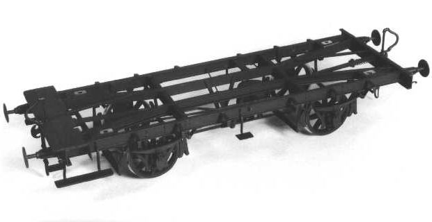
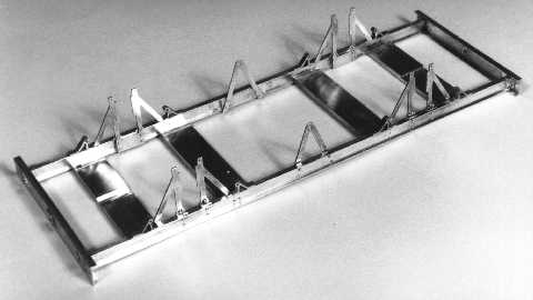
2. Frame and w-irons
I make the parts for the underframe from brass, subsequently they are assembled by riveting and soldering. The choice of material and design is arranged as to how the real vehicle is designed. If headstocks and outside solebars on the prototype are from wood I use solid brass for the model. If hot-rolled U-iron is used on the prototype I use milled brass profiles of nearest possible dimension; if necessary they are adapted (a 7x2 mm U-brass for a headstock is filed or milled to 6.7x2mm). For solebars I use I-brass (5x2 mm) on the model if prototype has solebars from hot-rolled I-iron.

You must choose whether inside longitudinal and transverse members are to be modelled or not. Earlier I have made underframes with inside members, but I don't feel that it's worth the trouble. I use crosspieces from flat brass bar or a through piece of brass sheet to fix the solebars and to fasten brake equipment etc. I use 4 or 5 crosspieces from 10x2 mm flat brass bar soldered to the solebars; I mill or file a notch in each end to contain the solebar's upper flange if it is from I-brass. Fixing holes are drilled in the outermost crosspieces, and notches to let the coupling shank go free are drilled and filed or milled. If I use a through piece of sheet it should be at least 0.5mm thick or provided with transverse stays, usually I use 1mm sheet. On short wagons I have used 1.5mm sheet to obtain sufficient weight, but then I had to make cutouts behind both couplings and buffers.
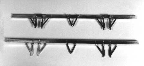
W-irons are made from 0.5mm brass sheet. They can be etched or cut and filed from four sheet pieces soldered together (the layer cake method). The two middle prongs are connected as the w-iron is in one piece behind the solebar, while the outermost prongs are free. When I-brass solebars are used the outermost prongs are bent to the outside at 90 degrees and soldered to the underside of the solebar. When solid solebars are used the uotermost prongs are fixed to the backside. In both instances vertical distance plates are put between the w-irons and the solebars so that there will be a distance of 0.2-0.3mm between the carrying springs and the w-irons. The springs must work freely and not rub against the w-irons, as this causes too much friction. When the solebars are from 5x2mm milled I-brass I make the distance plates from 4x1mm brass, see figure 2. The guide surfaces of the w-irons are filed smooth, the clearance between axle box and w-iron should be 0.1mm, and the edges are deburred carefully.
0.5mm holes are drilled in the lower ends of the w-irons' prongs; when assembling they are used for fixing keeper straps from brass under each axle box. It is an advantage to drill four 0.5mm or 0.6mm holes in the w-irons' top part, in the distance plates and in the solebars; thus the parts can be riveted together using 0.5mm wire or (better) 0.6mm brass rivets (from Old Pullman) before soldering. This way it is easier to control the position of the w-irons. It is essential that the axles are parallel to each other and at right angles to the vehicle's longitudinal axis; check with a setsquare and callipers before soldering that the w-irons are placed correctly.
When drilling small holes in thicker brass sheet it is necessary to cool the drill e. g. with methylated spirit. Otherwise the drill and the metal becomes so hot that the drill may jam inside the hole and break. The drill also keeps its cutting edges longer when cooled, thus it pays off. For applying coolant I use a 2ml disposable syringe with a 0.6mm hypodermic needle with the tip ground off (such are also used for liquid flux and oil).
Before the remainder of the underframe is soldered together, coupling plates are made and soldered to the headstocks together with their fixing bolts or rivets. The holes are filed square so they fit the coupling shanks. It is an advantage to drill all the necessary holes in the headstocks and solebars before assembling. Some details as the angle irons in the corners between solebars and headstocks are made from brass and soldered together with the main joints. Other details as the angle irons used for fixing the w-irons below the solebars are soldered on after the main joints are done.
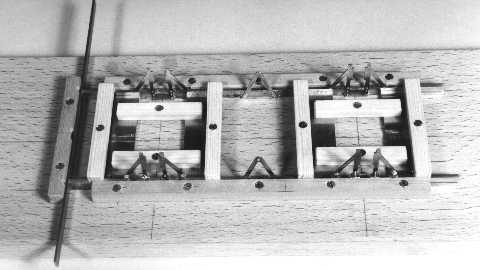
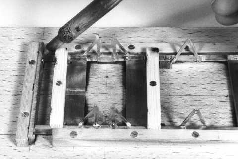
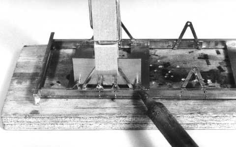
I usually make a wooden jig for holding the parts while they are soldered together. It can be made from a planed piece of hardwood, or from quality-grade plywood, and wooden lists; hardwood like beech lasts longer. This kind of jig can be used for soldering with an iron; it will eventually get too charred to use, so I make it the easiest feasible way. The jig must be able to hold the underframe parts in accurate position while measures and rightangularity are checked, and the joints are soldered. I use small wedges and clamping pieces from wood and brass screws to fix them, but take care where you put them as you must be able reach the solder joints with the iron. Flame soldering is not feasible with this kind of jig, then you would have to make a jig from materials that tolerate the heat, e. g. a ceramic material. I do, however, have no experience with such jigs. The alternative is to assemble all parts with rivets before soldering.
3. Wheel sets
I make my own wheel sets with wheel rim width and flange dimensions in exactly 1:45 scale; see figure 2, which shows a 974mm split-spoke wheelset. A similar set to the NEM standards is shown in figure 3. Both wheel sets have cylindrical axle journals, while the axle is longer than to NEM standards. Axles with pin-point bearings cannot be used for sprung wheel sets.
I use journal bearings with PTFE bushes, which run well with no lubrication. They wear very little and the friction does not increase with time, it may even drop as at the surfaces are worn smooth. In a track curve the axle end is pressed against the bottom of the bearing hole. The friction torque is increased considerably if the axle end is squared off and the axle touches the bearing bore at the journal's diameter. To prevent this I have used 1mm steel balls put between the axle ends and the bottom off the bearing bores, then the surfaces touch only at one point close to the axle's centre line, see figures 4a and 4b. I used 47mm long axles from 2mm silver steel with a spacer from 3mm brass tube between the wheels. This kind of axle is a little weak and can bend when the wheels are pressed on, and sometimes the tube wobbles because the inside diameter is a little too large. Furthermore it is difficult to press the first wheel onto the axle to the correct position so that the axle ends are of equal length.
Now I make axles from 3mm free-cutting mild steel, see figure 2; the ends are turned down to 2mm and provided with a rounded-off point, see also figure 4c. These axles are 49mm long matching the original 47mm plus two balls of 1mm each. The length of the 3mm-diameter part is made so that the distance between the backsides of the wheels is correct. It is important that the length of the axle measured on the journal surfaces is at least 2mm larger than the distance between the centre lines of the carrying springs (equals the distance between the centre lines of the solebars). Otherwise the axle boxes will tend to tilt on the axle causing uneven wear on the PTFE bushes and the friction to increase. I use a maximum of 45mm between the centre lines of the solebars.
4. Axle boxes and bearings
I cast axle boxes myself in white metal, but I have on occasions bought boxes made from white metal or zinc. Axle boxes can be fabricated from brass, but to make many identical parts in a tough way is not to my liking. Best of all are axle boxes cast in brass, but I haven't seen any Danish axle boxes made this way.
Holes for the bearing bushes are drilled; the diameter depends on the PTFE bush, I now use 2.9mm. The depth of the hole depends on the axle length and the distance between the backsides of the axle boxes when they sit correctly in the w-irons. The hole depth is measured with the aid of a turned piece of brass, see figure 4d. The depth can be made 0.1mm too small as the hole can later be drilled deeper. Use a drilling machine with depth stop and adjust the drilling depth gradually larger till the correct depth is reached. The hole should be drilled in the centre line of the axle box and at the correct distance from the top of the box.
During the drilling the axle box should be held in the correct position in a jig, or a small machine vice with distance blocks under the box. I now use a jig as shown in figure 5, thus the hole is placed correctly every time and I don't risk damaging the axle box. I first drill 2mm and then 2.9mm with a new drill, and cools with methylated spirit. Furthermore I drill a 0.6mm hole in the upper face of the axle box for the guide pin of the carrying spring; the holes are chamfered slightly.
I make the bushes from PTFE tube that is 3mm outside and 2mm inside diameters, and cut the bushes from this. The tolerances are, however, not ideal; to make the bush to sit firm in the axle box hole, I have to drill 2.9mm, but the inside diameter of the bush becomes too small when it is pressed into the hole.
I manage this the following way: A piece of PTFE tube is cut off 1mm overlength. In a piece of brass as thick as the final length of the bush a 2.9mm hole is drilled and chamfered on both sides. The bush is pressed inside hole; with a scalpel I cut the surplus length off plane with the surfaces of the brass piece. The hole of the bush is cautiously reamed with a sharp 2mm cylindrical hand reamer. The reamer is taken out, and a 2mm wide paper strip is together with the reamer put inside the hole, which is again reamed cautiously. The axle journal is tried in the hole of the bush - it must be an easy sliding fit without too much slop. The thickness of the paper strip determines the diameter of the bush hole (instead of reaming the bushes I now turn my axle ends to 1.9mm diameter). The bush is then pressed out from the brass piece by means of a turned mandrel. The bush is pressed into the axle box by means of a similar mandrel, so that it is guided well (see figure 4e).
Check that the w-irons are straight and parallel to the one at the other side, they can easily be bent during the work or when cleaning. Next the axle boxes are tried one by one in the w-irons; they have to move easily without too much slop. Otherwise the guide faces of the w-irons are filed a little until they are of equal inside width and the boxes fit; an equal amount has to be filed off the two guide faces on each w-iron. The axle boxes are taken out and are assembled with the wheel sets in the w-irons. If the boxes can't slide down in the w-irons, the bearing holes may not be deep enough. They can then be cautiously drilled a little deeper with a sharp 2mm drill in a pin vice. Remove the chips and try the wheel set and axle boxes once more.
5. Carrying springs and suspension
Working leaf springs are made to the same principle as the prototype springs as shown in figure 6. Each spring consists of a number of spring leaves, on coach and wagon springs the top leaf are at both ends provided with a rolled-up eye. On the second leaf from the top the ends reach the outer ends of the uppermost, the ends being cut off squarely. The remaining leaves have chamfered ends. The spring band surrounds and holds the bundle together, and a pin is inserted through spring band and spring leaves to fix them.
The number of spring leaves and the spring length are made as on the prototype. I used to make spring leaves from 2x0.3mm phosphor bronze strip, but I have on occasions made springs with thinner leaves. Each spring leaf is cut off with shears and the ends are squared off and deburred. In the middle of each leaf a 0.5mm hole is drilled and deburred. Bending around a piece of 0.6mm piano wire with flat-nose smooth-jawed pliers forms the eyes on the top leaf. The ends of the second leaf from the top are left square. On the remaining leaves the ends are chamfered and deburred.
The spring band can be bent from 2x0.2mm or 2x0.3mm brass strip around a rectangular mandrel of suitable size - a little smaller than the spring leaf bundle. At the bottom part of the spring band the brass strip is laid double, soldered and cleaned, and 0.5mm holes are drilled in top and bottom. I use a mandrel of size equal to the spring leaf bundle to try whether the size is correct. If the mandrel can't slip into the spring band or is too tight, the spring band is filed a little. If there is too much slop I usually discard it.
The spring leaf is formed with a suitable curvature; I try them against a plain plasticard template. The bundle is assembled on a /piece of 0.5mm brass wire and held together with flat-nose pliers. It is pushed into the spring band till the wire hits it, the wire is withdrawn and the spring leaves pushed further in until the holes align. A piece of 0.5mm brass wire with one end pointed is pushed through the holes in the spring band and leaves. The wire is cautiously soldered to the top of the spring band; the spring must still be able to work correctly. The ends of the wire are cut off and filed smooth, the lower end 1mm long as it is used to guide the spring in the axle box. The lower wire end is chamfered.
When the springs are assembled I measure the height of the springs, as they need to be of equal height. This is difficult because it is easy to compress them differently while measuring. I have, however, found the following method of use. I hold a spring between the two jaws of the callipers, so that the spring is slightly compressed. I then turn the callipers until one side of the spring is downwards. The jaws of the callipers are opened slowly until the spring drops out of the jaws. I make a note of the measurement of the callipers and measure the others likewise.
The springs also need to be of the proper height so that buffer height of the vehicle is correct. The springs are compressed a little under load so in order to calculate the spring height you have to estimate how much the deflection will be. At this point, bending them cautiously with the fingers can easily modify the height of the springs. The spring leaves should curve uniformly and lie against each other when the spring is loaded. It is best to make any adjustment now, as it is far more difficult when they are installed in the underframe.
The making and drilling of spring leaves and spring bands is time-consuming and tough. That's why I now etch the spring parts from phosphor bronze sheet; the preliminary work and the expense pays off if I need more than, say, two or three sets of springs of the same type. One advantage is that also the holes, and the bending lines on the spring band, are etched, and spring shackles are also included on the fret.
The spring brackets can be made from brass strip, solid brass or cast from white metal or brass. Older types of spring brackets for wagons can easily be bent from 2x0.3mm brass strip; it is not easy, though, to make them identical. Possibly a bending jig can assist but I have not tried this.
Cast spring brackets are drilled cautiously 0.6mm for the spring bolt, white metal brackets are a little fragile. Hold the brackets in a small jig or machine vice while drilling, and use a new, sharp drill in an electric drilling machine in a good drill stand, or a small bench drilling machine. The slide or quill has to move smoothly up and down so that you can feel how much force you put on the drill. Apply drilling coolant, cutting oil or methylated spirit to the drill during drilling, and take care to remove the chips by lifting the drill frequently, so they do not pack inside the hole. After drilling, the holes are deburred, the brackets cleaned and the base surfaces filed smooth.
I use a little jig, see figure 7, which ensures that the spring brackets are placed the right distance from the w-iron. The underside of the solebars are cleaned, two drilled spring brackets are placed on the mandrels of the jig, which is placed on the inner side of the w-iron with the brackets resting on the solebar. I use a clothes peg to hold the jig firmly to the w-iron. The spring brackets are soldered to the solebar; about soldering of white metal, see later. As an alternative, you can glue the spring brackets with cyanoacrylate adhesive, but it does not seem to last as well as soldering.
Spring shackles are made from 1.5x0.2mm brass strip or are cut from the etched fret. When making them from scratch two 0.5mm holes with the right distance between them are drilled in a brass strip using a drilling jig, and the shackles are cut and filed to shape. The spring bolts are two pieces of 0.5mm diameter brass wire cut 8-10mm long, which are put 5-6 mm into holes drilled in a piece of wood. The distance between these holes must be the same as in the spring shackles. A spring shackle is slipped over the wire pieces and soldered, the wire ends are cut off, filed to the right length (appr. 0.5mm) and deburred with a rotating steel wire brush in an electric miniature drilling machine.
The shackle is carefully pried from the piece of wood and cleaned; when eight shackles have been made, they and the springs are assembled. One spring and two shackles-with-wires are assembled in each set of spring brackets with the shackles to the outside. Onto the inside wire ends are pressed small pieces of thin paper and two more shackles. The inside shackles and the wire pieces are soldered cautiously together using very little solder. If you are too slow the outside solder joint will melt. The paper is torn from behind the inside shackles and the wire ends cut off. The entire assembly is cleaned, and the springs are tested for free movement. Now the axle boxes and wheel sets are tried with the springs; the wire ends in the spring bands must enter the guide holes in the top of the axle boxes. If anything isn't right it has to bet corrected now.
When axle boxes and wheel sets are assembled correctly in the underframe, I usually weigh it. I then turn the underframe around while holding the wheel sets so that they don't drop out, and put it on a plane and smooth surface (a piece of sheet glass or thick metal sheet will do). Put weight blocks onto the underframe so that the total weight corresponds to that of the completed coach or wagon, and see how the springs are compressed.
Check the height of the underframe, preferably to the lower edge of the headstocks at all four corners, but remember to add the flange height as the wheels now sit on their flange tops and not the threads. Is the height right? If not, the curvature and height of the springs has to be corrected. Check again and correct until the height is right.
Also try to run the wheels over pieces of sheet with different thickness. How do the springs work? Does one of the other wheels lift from the supporting plane? If a piece of thin paper is put under each wheel it is easy to feel whether the wheel is resting on the plane. Repeat the test with each of the other wheels. Coaches and wagons should be able to run across a piece of sheet that has a thickness of 1/100 of the model wheelbase, or a little less for large-wheelbase vehicles.
If during these tests only one wheel lifts from the supporting plane, the cause may be that the springs are of unequal height, or the underframe may be distorted. Examine and correct any errors, and repeat the tests. But if a wheel lifts during all the tests the springs may be too stiff; you may want to try with a thinner piece of sheet.
There is a small trick to make the springs softer. If the top leaves are curved a little more than the others, only the top leaves will be active at small loads and the spring is softer. Only when the load increases the space between the top and lower leaves is closed and the lower leaves become active. Try this technique, but preferably the difference in curvature should be such that the spaces are closed or almost closed when the vehicle stands on a plane; otherwise the springs don't look right.
6. Buffers
I make the sprung self-contained buffers myself. Some buffer types can be bought; you should investigate whether they are satisfying before you start making your own.
The easiest to make are the old Sealand buffers with closed buffer housing, see figure 8. They are made with turned housings from brass, to which are soldered mounting flanges from brass sheet with holes for fixing bolts drilled into them. Flanges and housings are glued on the headstocks, which are drilled 3mm in advance; the boltholes are drilled through and bolt ends are glued into them. The buffer shanks are turned from brass, the buffer heads are cut or turned from 0.3mm brass sheet, soldered to the shank and the edges rounded.
Half of the buffer heads are domed in a small pressing tool before soldering. Buffer springs are made from 0.2mm piano wire, which is wound tightly around a mandrel; the spring is stretched, pieces are cut off overlength and the ends are ground smooth with a cutting disc in a miniature drilling machine. Buffer shanks with heads and springs are assembled with M1 nuts that are secured with a little varnish.
I also make DSB self-contained buffers with open buffer housing as shown in figure 9. This type of buffer housing is a little more complex than the Sealand variety; they could be found also with shanks as in figure 8. The housings are made in 3 parts, a turned and milled open housing with four prongs, a flange and a turned bush and dummy spring.
The housings can be made from pieces of tube, which are slotted twice and the prongs bent out, but it is difficult to make it look properly using this method. Examine prototype buffers to see how they are made. More recently, I have made cast this type of buffer housing as one part in white metal. They function rather well, but need to be drilled through 1.6mm and provided with a stop bush for the spring, which is a little tricky.
The buffers must work without friction and the springs must not be too stiff. I have heard an old rule about buffer springs, that they shall be compressed halfway when the vehicle is stood vertically on it's two buffers in one end; this seems to work well. I make my buffer shanks 1.5mm diameter; this corresponds to 68mm on the prototype. Older coaches and wagons had 65mm buffer shanks. Newer and larger coaches and wagons had 75mm buffer shanks which amounts to 1.7mm in 1.45 scale.
7. Couplings
I don't use automatic couplings, only screw couplings. The coupling hooks are cast from white metal; the springs are made from 0.3mm piano wire, and should not be too soft. The hooks and springs are held in place by small washers with square holes to fit the shanks, and pins from 0.5mm brass wire are inserted into holes drilled in the shank. The pins are secured by bending the ends or applying a little varnish.
The screw couplings are made with shackles etched from 0.5mm brass sheet, and the coupling screws with nuts are cast from white metal, see figure 10. The coupling bolts and washers are turned from brass and soldered to the shackles while these are held with tweezers and a spacer block in between. Remember to put the hook on first. The white metal screws are the weakest part of the design, and I consider having cast some from brass after a new master. These couplings work excellently and are easier to couple than old-fashioned three-link chain couplings because they don't tilt.
8. Brakes
Brake hangers are etched or cut and filed from 0.5mm brass sheet, the top ends are bent over and soldered or screwed to the underframe. Brake blocks are mostly cast from white metal, but I have on occasions made some from a turned brass ring that is cut and filed to shape. Brake blocks from metal need to be adjusted carefully or the surfaces protected with a hardwearing varnish so that they do not short-circuit the wheel sets.
Brake transverse rods can be made from 1mm brass sheet with turned ends, which are soldered into holes drilled in the rod ends. The holes for pull or push rods are drilled 0.7mm; the transverse rods can be reinforced at the holes if need be by soldering on pieces brass strip. Brake brackets are cut and filed from 0.5mm brass sheet and soldered to the underframe the same way as the w-irons. If there is a brake bracket placed close to the centre line, it can be fixed using a piece of brass angle. The brake axle is turned from brass, the arms cut and filed from brass sheet and hubs made from small turned rings, both soldered to the brake axle.
Push rods are turned from brass and the forked ends are filed to shape and drilled. The notches are filed with a flat file that is ground on both sides, so that it cuts a notch 0.5mm wide. The thin end of the rod, which passes through the transverse rod, is 0.7mm diameter, while the thick part is 1.3mm. Pull rods are made from two 1.5x0.3mm brass strips that are joggled and soldered together so that the forked ends are formed. The rods are filed to shape the thin ends to 0.7mm width and rounded so that it can slip through the 0.7mm holes in the transverse rods. Lastly the holes in the forked ends are drilled.
The brake screw is normally fixed to the body, while its lower bearing, which is cut and filed from brass, may be fixed to the underframe. The screw is made from a piece of M1.2 or M1.4 threaded brass (possibly from a suitable long screw) and 1mm brass wire. The brake handle is cut and filed from 1mm brass sheet and the upper bearing is turned and filed from solid brass. The angular arm and the pull rods are made from 0.7mm and 0.5mm brass sheet respectively.
The vacuum cylinder and valve is cast from white metal; the tank is cast from white metal or turned from brass. Brake pipes are from 1.0mm or 1.1mm brass wire with a few turned fittings and suspensions formed from 0.2x1mm brass strip or cut and filed from 1mm brass sheet. Connecting hoses are made from a spring wound from 0.25mm piano wire, and pressed onto 0.8mm pipe ends.
Standpipes at the ends are from 1.0mm or 1.1mm brass wire with turned fittings that are silver soldered in a jig, and the fittings are filed to shape after soldering. The silver soldering is necessary as it otherwise will fall apart when soldering to the underframe; they are a little time-consuming to make, so this is yet another item I consider having cast from brass. Vacuum pipe couplings are filed from brass and the coupling hoses are made from a spring as described before. The coupling heads are soldered to keepers from brass strip; they are folded around the standpipe and soldered.
Wooden brake blocks are on the model made from polystyrene plastic sheet. The push rod for the hand brake is made from two pieces of joggled brass strip soldered together as described for the pull rods. The hand brake axle and its bearing are made from a turned brass part and a piece of brass angle, soldered together and glued to the solebar. The hand brake handle is cut and filed from 0.5mm brass sheet, thinned down to 0.3mm at the outer end. The brake handle guide is made from brass strip and both ends soldered to the solebar. It can be a little difficult to place it correctly; on the prototype the upper end was normally fixed to the body. The upper end must be extended and bent so that it lies beneath the floor, and soldered into a notch filed in the upper edge of the solebar.
On coaches and wagons with vacuum and screw brake, the transverse rods are not soldered to the brake hangers but the ends are just put through the holes in the hangers, which need to be adjusted carefully. In the same way, pull and push rods are not fixed to the transverse rods but are just put through the holes in the transverse rods. This way the brake parts can be adjusted at the final assembly. As the pull rods often pass beneath the axles, it is necessary to remove some of the brake rods to get the wheel sets out.
9. Footsteps and footboards
Footsteps and footboards are cut and filed from brass sheet. Differently thickness are used: Thin footsteps from steel are made form 0.2mm brass sheet, thicker wooden footsteps from 0.7mm brass sheet, and footboards from 0.8mm brass sheet. On some wooden footsteps and on footboards 0.7mm brass kickboards are soldered to the inner edge. Brackets supporting only one footstep or footboard are bent from 1mm brass wire. It is, however, a little difficult to make them identical, a bending jig can aid here. This type of footboard bracket is soldered into a hole drilled in the solebar just above the bottom flange, and a piece of brass strip is added to the face of the solebar above the bracket.
Footboard brackets of other types are cut and filed from 1mm brass sheet using the layer cake method. After shaping they are separated by heating with the soldered iron, and any solder is cleaned off; the edges are rounded as appropriate. After that they are soldered to the footsteps and footboards, it is then easier to guide the parts when they are soldered to the underframe. The brackets can be soldered to the footsteps and footboards in a simple wooden jig. When the footboard brackets are soldered to the face of the solebars, see figure 11, or the headstock, they are held with common wooden clothes pegs that are shaped to fit.
10. Handrails
The only handrails on the underframe are normally those placed below the headstocks to assist shunting crew moving under the buffers. Older coaches and wagons did not originally have these. They are bent from 0.4mm brass or phosphor bronze wire, inserted into holes drilled in the headstock and soldered. The holes can be drilled before headstocks and solebars are soldered together. The wire ends should be cut off at the proper length before soldering, as they are difficult to reach with cutting pliers after soldering. When soldering the distance to the headstock is kept using a wooden list or plywood of suitable thickness.
11. Nut and bolt heads and rivets
I put on any rivets and nut-bolt ends that are visible at normal viewing angle on the underframe. Rivets are turned from round brass bar, or I buy turned brass rivets. Nut and bolt ends are turned and filed from round brass bar, or I buy nut and bolt ends cast from brass or moulded from plastic. They are inserted into drilled holes; brass rivets and nut-bolt ends are soldered, but can be glued if you prefer. The plastic bolt ends are cheaper, they can, however, first be installed when all soldering work is done; they are glued with cyanoacrylate adhesive.
12. A little about soldering
I normally use 60/40 solder (60% tin and 40% lead), preferably solid wire solder but flux-filled wire can also be used. This solder melts at 183-188°C and the soldering temperature is 235-275°C. I generally use BERA liquid flux. Do not use paste flux as it uses Vaseline basis that is difficult to clean off completely, then the paint won't stick properly to the surfaces. I use a Weller type TCP-50 temperature-controlled soldering iron 24V/50W with type 7 tips (370°C). When I need more heat than the Weller can supply, I use a small gas burner.
There are a few prerequisites to good soldering; the surfaces to be soldered must be absolutely clean, mechanical cleaning with file, abrasive paper or glass burnisher is most efficient. Chips, dust and abrasive residues are removed with a clean, dry paintbrush. A suitable flux is applied to the surfaces to be soldered before heat is applied. The parts should be held steadily during soldering; a jig, small wooden blocks and drawing pins, or binding wire can be used, or you can drill holes in the parts to be soldered and use pins or bits of wire in the holes for guidance. The parts should be heated swiftly and uniformly to the soldering temperature with a cleaned and lightly tinned soldering iron or a gas flame. When the flux has fizzed off a little solder is applied, preferably the solder shall be heated by the parts to be soldered, not by the iron or the flame. One other method is to add a small sliver of solder to the joint before heating; it should be placed opposite to the iron or flame. When the solder flows, the soldering iron or flame is removed at once so that the solder is not overheated.
White metal can be soldered to brass with solder 60/40; be careful, though, that the surfaces to be soldered are scrupulously clean, apply liquid flux and put a sliver of solder next to each solder joint. Heat up the brass part with the soldering iron. When the solder melts and flows into the joint remove the soldering iron immediately. Don't ever touch the white metal with the soldering iron as small parts like spring brackets melts very fast.
After soldering, the parts should be cleaned thoroughly. I first clean with warm water with a little detergent added using an old toothbrush, then either with scouring paste or pumice powder and a little warm water, rinse with clean warm water, clean again with warm water and detergent and at last rinse thoroughly with purified water. The water is shaken off or blown off with clean compressed air, and the part air-dries beneath a piece of aluminium foil so that dust does not settle. The parts worked on should be cleaned after each day's soldering work.
13. Painting the model
The underframe is taken apart as far as possible and the parts are cleaned and dried as described before. If the parts are not cleaned thoroughly, the paint will not stick well to the surfaces. You can prime the metal parts but it is my experience that most primers don't stick much better than finishing paints. As I want as thin a paint layer as possible, I don't prime.
I prefer matt and semi-matt paints; many of the matt paints on the market (e. g. Humbrol) do not stick well on brass. Normally the gloss paints stick well so you can actually prime with gloss paint and finish with matt paint or lacquer. I am, however, doing it another way as I have chosen paint from the US company Floquil. These paints can't be bought in Denmark and can't be sent from the USA because of postal restrictions as it is flammable, but I buy it by mail order from Old Pullman Modellbahnen in Switzerland. Floquil paints stick very well to brass and wears well. Floquil have also started making a new type of acrylic paint, "Polly Scale", which I am looking forward to trying it on my models.
I normally use dirty black colours and spray it with an airbrush. Surfaces that are not to be painted are masked with ordinary masking tape; axle boxes are put on matches shaped to receive them, and axle ends are covered with pieces of plastic tube. The underframe is screwed to a bent metal strip with a handle screwed on. The paint is thinned with Floquil's thinner, Dio-Sol, so that it dries quickly after reaching the surface. This way the paint does not seep in between the leaves of the carrying springs. If you brushpaint the springs must be painted with an almost dry paintbrush to get a similar result. I only spray on one layer; the paint dries so quickly that after a few minutes you can spray the surface once more if the layer is too thin. The paint should preferably dry one week before the parts are handled further or assembled. Masking tape should be removed after 24 hours, as it will otherwise leave a residue.
14. Assembly
When the paint has dried thoroughly the last of the masking is removed. Axle journals, wheel threads and flanges that are to be bright, are cleaned and polished, and a very thin layer of light machine oil is applied using a paper towel. The function of the leaf springs is checked and all parts are assembled. Check that the axle boxes slides easily in the w-irons and the parts fit well together. If there are any accumulations of paint that hamper movement they can cautiously be sanded smooth with fine abrasive paper (grit 500-1000).
Keeper straps for the w-irons are made from 1x0.3mm brass strip. Two 0.5mm holes are drilled in each so they correspond with the holes in the w-iron, and they are fixed using rivets from 0.5mm copper wire. One end of the copper wire is deburred and slipped through a hole, the other end is cut off so that the wire protrudes approximately 0.5mm at each end. The ends are riveted by cautiously squeezing both with a pair of flat pliers, just enough for small heads to form on the wire ends and hence to fix the keeper straps. Finally buffers and couplings with their springs are assembled; nuts and pins are secured with a little varnish.
Keeper straps and rivets, and any damage to the paint, should be painted now with a brush, normally I apply two thin layers when brushpainting, drying time between layers should be at least a couple of days. When the paint has dried the lettering is applied, and the underframe is now ready to receive the completed body. Weathering is applied according to the age of the vehicle and the likes of the builder.
Useful addresses
- Old Pullman Modelbahnen, Im Kreuz, Postfach 326, CH-8712 Stäfa, Schweiz, http://www.oldpullman.ch/: Brass rivets 0.4-0.6-0.8-1.0-1.2mm, bolt ends from plastic, Floquil and Polly Scale paints.
- Wm. K. Walthers, Inc., 5601 W. Florist Avenue, Milwaukee, WI 53218-1622, USA, http://www.walthers.com/: Bolt ends from plastic and brass, rivets from plastic, Polly Scale paints.
- Brdr. A & O Johansen, Rørvang 3, DK-2620 Albertslund, Denmark, phone +45 43 86 00 00 (service centres across the whole country): Silver solder 5, BERA liquid flux.
Changes:
2008-03-15: Updated to HTML 4.01 Strict.
2009-01-02: Typeface updated.