Derailments
- or how do I keep my train on the track?
by Erik Olsen
Please notice that MOROP's NEM norms and NMRA's standards are revised from time to time. Because of this the content in this article may be imprecise, please only use the current version of the NEM norms and the NMRA standards.
Content:
- Introduction
- What may go wrong?
- Derailments on plain track
- Derailments in points and crossings
- Standards for wheel sets
- Standards for flanges
- Standards for plain track
- Standards for points and crossings
1. Introduction
Why does my train derail in that particular point? Many railway modellers have undoubtly asked this question from time to time. To give a specific answer you need to thoroughly examine wheel sets and track; but it is possible to give general answers to the question: What may go wrong?

In the following I will try to explain a little about the most important factors in what the prototype railways call running safety. The topic is of course not as important on a model railway as on the prototype but who won't gladly avoid derailments on the model railway?
This explanation is based on the most widely used scale and gauge in Denmark, H0 scale using 1:87 scale ratio and 16.5 mm track gauge. The standards used are NEM 310 Wheel set and track, NEM 311 Wheel profile, NEM 124 Points and track crossings with non-movable rail crossings and NEM 127 Non-movable obtuse crossings for straight track crossings.
Of course you can use other standards i. e. NMRA S3, S4 og RP25 or one of the new exact-scale standards as H0pur or Proto:87, or you can make your own standards. It is explained in the article how they are designed and function in practice.
In this article I use NEM standards as a basis as they are the most widely used in Denmark. Please note that Märklin H0 use standards that are different; they are described in NEM 340. The principles are the same as NEM 310 but the measurements differ. This is why Märklin wheel sets cannot run through points to NEM 310.
The NEM standards can be found at http://www.morop.org/de/normes/index.html (these are in German, only a few have been translated into English). The NMRA standards can be found at http://www.nmra.org/standards/.
2. What may go wrong?
There are two main groups of causes for derailments:
- On plain track caused by
- too large back-to-back distance B on a wheel set
- wrong flange profile
- the vehicle is twisted
- faulty wheel suspension
- faulty couplings
- horizontal displacement of rail ends in a rail joint
- vertical displacement of rail ends in a rail joint
- too large distance between rail ends in a rail joint
- the two rails of a rail joint are at an angle to each other
- too small track gauge
- too abrupt change of track gauge
- too small curve radius
- too abrupt change of curve radius
- too large twist in the track
- too abrupt change of the level of the track
- In points and crossings (in addition to those mentioned above) caused by
- too large check gauge K on a wheel set
- too small back-to-back distance B on a wheel set
- too small wheel width N
- too wide crossing nose
- too small track gauge at the switches
- too small distance between the open switch tongue rail and the adjecent stock rail
- the switch tongue rail is not fastened properly
- the crossing nose is not in line with the wing and closure rails
- too small track gauge at the crossing nose
- too small check gauge C (check rail placed wrong)
- too large distance S over check and wing rail faces
- too large crossing flangeway
- malformed check or wing rails
Often a derailment is caused by more than one defect at the same time. The most efficient way to handle derailments is to examine both the train and the track at once to establish any defect that may have had influence on the derailment. If you don't have time to repair defects immidiately you should mark the defect or make a note of it so that it can be repaired whithout missing anything.
3. Derailments on plain track
Derailment frequency often depend on the speed of the train. Many defects at the track and often also at wheel sets primarily has influence at high speeds. This means as on the prototype that sidings where the speed is low can be of lesser standard than main tracks, and, of course, that one should actually run slowly in sidings!
Locomotives and rolling stock should be checked: Are wheel sets, suspension and couplings in correct working order? On bogie stock the bogies should be checked for free movement and if the body is able to rock a little sideways. The best solution often is to have one of the bogies to guide the body while the other bogie may be without side guides so that it can follow track irregularities freely. Four-wheeled stock should be checked for twist; place the coach or wagon on an even surface and check that all wheel flanges touch the surface. Pieces of paper can be inserted between the plane surface and the wheel flanges to check this. If the coach or wagon twists more than 0.3 mm per 100 mm wheel base it should be corrected.
The track gauge should be checked both before and after the track is laid down. If track with plastic sleepers has been stored in too hot conditions the sleepers can have warped and the gauge subsequently too small. This happens mostly with the lesser types of track as it depends on the plastic type used.
Curve radii should be chosen for the stock that is to run on the track. If a piece of track is laid with a curve radius that a given locomotive can only just run through the radius must be the same throughout the curve. Note that bends in rail joints may reduce the effective curve radius considerably. If you use flexible track it is wise to use jigs for laying small radius track curves; such jigs can be easily made from 1.5-2 mm ploystyrene plastic sheet, or they may be bought in a drawing equipment shop.
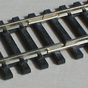
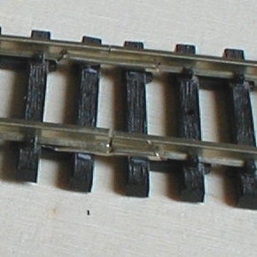
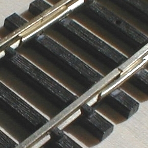
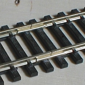
Rail joints should be made with joiners that fit well to the rail so that there can be little vertical or horizontal displacement of the rails relative to each other (in my experience less than 0.2 mm displacement seldom gives problems). The rail ends should be close to each other, the gap should not exceed 0.5 mm. A space should be cut out for the joiner in the sleepers next to the joint otherwise the rail ends will be pressed slightly upward. Extra care should be taken with insulated joints as many plastic joiners fit badly to the rail; instead of using plastic joiners insulated joints can be glued using epoxy adhesive. For transitions from one rail size to another speciel rail joints should be made and the joints soldered.
In straight track and large-radius curves small kinks at rail joints seldom give any problems but in small-radius curves kinks can lead to derailments. One way to avoid kinks when using flexible track is to lay the main curve without rail joints. If that cannot be helped the joints may be soldered before the track is curved and laid down. Insulated rail joints in small-radius curves should be avoided, or the rails may be dismantled from the sleepers and pre-curved before being assembled and laid down. If the track is already laid down and fastened it is difficult to curve the rails without kinking them. It may be possible to force the rails into the proper position using nails and small wooden blocks; after this the rail joints may be soldered and the nails and blocks removed.
Twisting the track cannot be avoided especially if banking in curves is used. The twisting should, however, be held as low as not to give problems. As a rule of thumb the added twisting of the track and the rolling stock should not exceed 60-70% of the flange height for the wheel base of any vehicle. An example: If the wheel base of a four-wheeled wagon is 100 mm and flange height is 1 mm the added twisting of the wagon and the track should not exceed 0.6-0.7 mm in 100 mm. Normally the twisting of a wagon can be held below 0.2 mm; this means that the track may twist 0.4-0.5 mm in 100 mm.
This must be seen in relation to how transition curves and banking in curves are made. According to NEM 113 the shortest possible transition curve is 275 mm long equal to the length of the banking ramp and according to NEM 114 the maximum banking is 1 mm. This gives a twisting of the track of 1 mm in 275 mm or 0.36 mm in 100 mm. Banking and especially the ramps thus need to be made carefully.
This situation is the only one where wheels with high flanges has a positive function when used on long wheel base rolling stock. If banking is not used, or if minimum curve radius is 600 mm or more (the longer transition curve means that the twisting of the track is less) and the track can be laid down reasonably evenly, it is possible to use low flanges as in NEM 311 using D = 0.6 mm (or NMRA RP25).
Abrupt changes of the track level may be the cause of derailments and then mainly vertical kinks in the track. Transitions from horizontal track to a gradient or between different gradients should be rounded off generously.
Track twisting and abrupt change of track level may only be avoided if the base of the track is made properly. Before the track is laid down a) a spirit level should be used to check that the base is level crosswise at each support, b) a ruler at least 500 mm long should be used along the track to make sure that transitions are rounded sufficiently. Any errors can be mended by planing, sanding or by filling with putty.
Banked curves and ramps should be built on a level track base and the banking made using a piece of stripwood under the outer rail and filling with putty, or a wedge-formed piece af material as a shim. When laying down track and points of different height card shims or similar should be used so that the rail tops are at the same level.
If the track is laid down before defects at the track base is detected the only proper way is to pull up the offending piece of track, rebuilt the track base and lay down a new piece of track.
4. Derailments in points and crossings
In points and crossings may occur derailments that differ from those mentioned above in that the derailments do not depend on the speed of the train, i. e. that they also occur at low speed. This kind of derailments can be easier to identify as they often can be repeated and studied in detail.
Derailments in a set of switches may be caused by defects at the tip or the heel of the tongue rail or because the gauge is too small so that the wheel sets jam.
The tongue rail tip should be quite narrow, 0.1-0.2 mm, and the edge should be filed at an angle of 10-15° to vertical. The height may be reduced a little, 0.2-0.3 mm, at the tip. All edges should be rounded; when running a finger along the inside when the tongue is placed against the stock rail the edge should be quite smooth. The throw mechanism and stretcher bar should be made such that the tongue rail is held sequrely against the stock rail.
The switch heel joint should be made such that the tongue rail is held securely and in line with the closure rail. If the are not in line a wheel may strike the end of the tongue or closure rail and derail. The tongue rail may be fastened using a rivet which must not be loose. If the rivet is loose it may be carefully riveted over without becoming too tight so that the movement of the tongue rail is hindered. This should be checked before the point is laid down as it can be impossible to repair properly afterwards. If the tongue and closure rails are not in line one of them may be bent carefully (check the gauge). The closure rail may be glued securely in its new position.
When a tongue rail is open the distance to the stock rail should be large enough that passing wheels do not strike it.
Derailments in a crossing often are caused by the crossing nose or the check rails being placed wrong, or the back-to-back distance on a wheel set may be too large or too small.
The crossing nose should be in line with wing and closure rails. This kind of defect is not as common on manufactured as on self-made points. If the crossing nose is placed too far forward it is possible to file off the sides such that the running edge will be in line. As the wheel threads are conical the crossing nose may be filed down on the first 3-4 mm so that it is 0.1-0.2 mm lower than the wing rail; this makes for a smoother run through the crossing. All edges should be rounded.
The function of the check rails is to guide the wheel set through the right side of the crossing nose. Without check rails a wheel set may hit the crossing nose and derail especially in the curved road of the point. To avoid this situation the check rail is placed in the minimum check gauge C from the crossing nose so that the flange does not hit it but is guided smoothly past.
The check gauge C of the crossing relates to the check gauge K on the wheel set; C should be larger than or equal to K. In NEM 310 is defined Cmin = Kmax = 15.2 mm. This rule is valid for most model railway standards for wheels and track (on the prototype there is a small overlap). If a wheel set derails against the crossing nose the defect must be sought by examining the check gauge of the wheel set as well as that of the crossing.
If the check gauge K of a wheel set is too large the wheels can be carefully pressed together on the axle. Check that the two axle ends are of equal length. If the check gauge C of a crossing is too small the check rail must be moved away from the crossing nose. If this is not possible a strip of plastic or metal of the proper thickness may be glued or soldered to the outside of the check rail. After this is done any excess glue or solder should be removed and all edges rounded.
Wheel sets must also be able to pass the check and wing rails without jamming. A little play is necessary as wheels sets are angled on curved track. If a wheel set derails because it runs up and over the check and wing rails the defect should be sought by checking the back-to-back distance of the wheel set and the distance over check and wing rail faces.
If the back-to-back distance B on a wheel set is too small, the wheels can carefully be pressed together on the axle. If the distance over check and wing rail faces is too large, small amounts of material may be filed of the check or wing rail faces. Measure the check gauge C and the crossing flangeway F to determine which of the faces should be filed. After filing all edges should be rounded.
The wing rails are placed in the distance F (crossing flangeway) from the crossing vee. In front of the crossing nose ther will be a distance of twice F plus the thickness of the crossing nose between the two wing rails; a wheel must be able to pass this gap. If the wheel width N is larger, the wheel will run on the wing rail farthest from the flange until it reaches the crossing nose.
If the width af the wheel, however, is less it will drop down between the wing rails. This need not lead to a derailment but makes for rough running. This is why the crossing flangeway should not exceed Fmax and the wheel width should not be less than Nmin. The wheel width on some manufactured models are less than Nmin; then it becomes important that the crossing flangeway is made as small as possible.
The ends of check and wing rails should be bent into the track in a flat angle and the distance from the ends to the running rails should be large enough for a wheel not to hit them. There should be no burrs or sharp edges. If the ends of check and wing rails are bent too sharply rough running will result.
5. Standards for wheel sets
As an example is used a common coach or wagon wheel set to NEM 310 and flange profile to NEM 311, the flange height is 1.0 mm. NEM 310 and 311 for 16.5 mm gauge allow a flange height from 0.6 mm to 1.2 mm.
In figure 4 is shown which measurements are defined in NEM 310 using the designations from the standard. It is drawn using the exact measurements indicated as it is in this form the wheel set may cause trouble in combination with a defective point or crossing. The measurements are designated:
- P: Distance from rail surface (SO) to measuring plane (P = 0.25 mm)
- N: Wheel width (Nmin = 2.8 mm)
- T: Flange thickness (Tmin = 0.7 mm, Tmax = 0.9 mm)
- D: Flange height (Dmin = 0.6 mm, Dmax = 1.2 mm)
- B: Back-to-back distance (Bmin = 14.3 mm)
- K: Check gauge (Kmax = 15.2 mm)
Please note that values for Nmax, Bmax and Kmin are not given. This does not mean that they may be chosen freely but rather that they are indirectly limited by other measurements. As an example: In practice Kmin is limited to Tmin + Bmin = 0.7 + 14.3 = 15.0 mm and Bmax is limited to Kmax - Tmin = 15.2 - 0.7 = 14.5 mm.
But take care as one cannot use values calculated this way for construction, for if you made a wheel set using B = 14.5 mm and T = 0.9 mm the check gauge K would be 14.5 + 0.9 = 15.4 mm which is larger than Kmax - that won't do!
As shown in figure 1 and 2 measurements B and K are the most important to safe running through rail crossings. It may lead to rough running through rail crossings if N is less than Nmin.
The check gauge K cannot easily be measured directly. Instead the back-to-back distance B and the flange thickness are measured and the check gauge calculated as K = B + T. An example: B = 14.5 mm og T = 0.8 mm is measured, the check gauge is calculated as K = 14.5 + 0.8 = 15.3 mm - larger than Kmax, that won't do! The flange thickness T may be measured as shown in figure 6.
6. Standards for flanges
The flange profile is defined in NEM 311. As may be seen from figure 2 some designations are the same as in NEM 310. The function of the measurement P, the distance form rail surface to measurement plane, is more clearly seen; this auxiliary measurement define the flange thickness T and hence the important check gauge K unambiguously. Otherwise the gauging point would lie within the fillet making the flange width impossible to measure accurately.
The most important detail in the flange form is the conical front side (to the left in figure 5). The angle relative to the rail surface (SO) plane should not exceed 70°; The angle may be a little less, in practice 60° does not give any problems. A 60° angle in fact leads to safer running if used with low flanges. The purpose is that the top of the flange does not make contact with the rail head; with tall flanges and small-radius curves this may happen, thus the top of the flange should always be rounded smoothly (R2), i. e. with no burrs or edges.
The thread angle and the fillet between thread and flange (R1) makes the wheel set run steadier. Particularly the fillet if larger than the rounded edge of the rail head may cause less derailments because it will keep the flange at a distance to the rail head.
The back side of the flange may be chamfered as shown; Q should be larger than or equal to P, i. e. the chamfer must not be too big. The chamfer can lead the wheel set more gently past check and wing rails. As mentioned before it is important that there are no burrs or edges where the rounded flange top and the backside fillet meets.
7. Standards for plain track
In NEM 310 the track gauge is shown as G (nominal) = 16.5 mm and Gmax = 16.8 mm. On straight track it is recommended to use 16.5 mm; in curves the gauge can be widened a little to avoid jamming of long wheel-base stock. A minimum value is not defined but in my experience the gauge should not be less than 16.4 mm on straight track and 16.5 mm in curves.
Apart from this there is not much help to get in NEM. There are standards for minimum curve radii depending on stock wheel base and for transition curves but nothing on how large errors and tolerances are acceptable when laying and maintaining track. But a little common sense may guide us on the way (section 3).
8. Standards for points and crossings
Three NEM standards are relevant for points and crossings: NEM 310 Wheel sets and track, NEM 124 Points and crossings with non-movable rail crossings and NEM 127 Non-movable obtuse rail crossings for straight crossings.
As can be seen from figure 7 check rails are always placed relative to the crossing nose. The measurements are designated as:
- C: Check gauge (Cmin = 15.2 mm)
- S: Distance over check and wing rail faces (Smax = 14.1 mm)
- F: Crossing flangeway (Fmax = 1.3 mm)
- H: Flangeway depth at crossing (Hmin = 1.2 mm)
- F0: Check rail flangeway (derived measurement)
As a rule of thumb a check rail flangeway of F0max = G - Cmin may be used. An example: If the gauge is 16.6 mm F0max will be 16.6 - 15.2 = 1.4 mm; in practice a smaller value may be chosen, i. e. 1.3 mm so that C = 15.3 mm. If F = 1.3 mm then S = 15.3 - 1.3 = 14.0 mm; this is less than Smax, ok.
The check gauge C is not easy to check directly. Instead the gauge G and the check rail flangeway is measured and the check gauge is calculated from C = G - F0. An example: If G = 16.5 mm and F0 = 1.3 mm then C = 16.5 - 1.3 = 15.2 mm - acceptable.
Figure 8 shows the design of check and wing rails to NEM 124. The important thing here is that the wheel set is guided smoothly through check and wing rails, i. e. the inlet angle is flat, the rails have no burrs and edges are rounded.
Figure 9 shows how the open switch tongue rail must lie at such a distance to the stock rail that it is not struck by passing wheels. This is not least important if the tongue rail has a different electrical polarity from the stock rail and if contact may lead to a short curcuit; if the distance is too small the train may derail if running at high speed.
Figure 10 shows the design of obtuse rail crossings to NEM 127; obtuse crossings are used in track crossings and slip points. In this type of crossing there is a certain distance where a passing wheel set is not guided safely they should be constructed very carefully. As in normal crossings there should be no burrs and edges that may hamper the passage of a wheel set.
Changes:
2008-03-15: Updated to HTML 4.01 Strict, the resolution of the figures has been changed.
2009-01-01: Typeface updated.