Load on DC motors in model locomotives
by Erik Olsen
How do small DC motors in model locomotives respond to mechanical load? The answer depends on which type of motot is used and how the motor is controlled.
1. Motor types and load diagrams
In the following some types of DC motors and their load diagrams, i. e. how the motor speed changes when the load on the motor varies and the supply voltage is held constant. The motor speed is measured in rpm and the load is measured as torque in Nmm (newton-millimeter) on the motor axle end.
1.1 The shunt motor
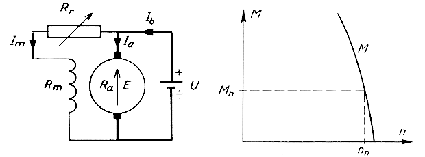
The shunt motor is not used for model railways but is mentioned here to complete the picture. The shunt motor cannot run on AC.
1.2 The series motor
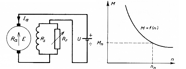
The series motor is still used in older models from Märklin. The series motor can run on AC as the current through the armature and the field winding is in phase, and it is hence also called the universal motor. Large series motors shall not be allowed to run unloaded as they may run much too fast and be damaged.
1.3 Motor with permanent magnet
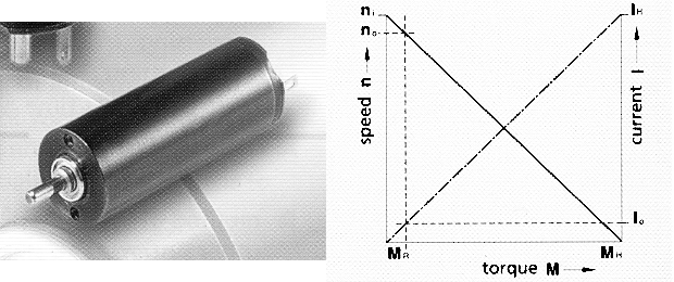
Motors with permanent magnet are found in various designs. Older designs look like the shunt motor only that a powerfull permanent magnet is used instead of the field winding. Newer designs have tubular permanent magnets. The newest design is the so-called micro motor which have an ironless armature and a cylindrical permanent magnet placed inside the armature. The different designs performance in principle the same way.
All motors should not be over-loaded in longer periods of time as they will be damaged by the excessive heat generated. The maximum safe continuous motor load can be drawn into the load diagram.
2. Load diagram of the locomotive
2.1 Principle
Usually the motor and gears are built into a locomotive such that there is a given mechanical gear ratio from the motor axle to the driven wheel sets. This means that the motor speed is proportional to the speed of the driven wheel sets.
While in motion there are mechanical losses in the bearings, gears etc. of the model locomotive due to friction. Losses may be calculated in two ways, either as constant (friction in wheel bearings, current collectors and similar) or proportinal to the torque (friction in gears, worm/gear, gear axle bearings etc.). This distinction makes it a lot easier to calculate how losses influence load performance.
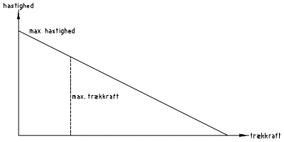
This means that a load diagram can be designed for a given locomotive in the same way as for the motor alone. For the motor the rotational speed and torque is used, whereas for the locomotive linear speed and pulling force is used. The linear speed is measured in scale kilometres per hour and the pulling force in mN (millinewton).
For simplicity are shown load diagrams for DC motors with permanent magnet but the principles applies to series motors as well only that the load line will be curved.
There are two factors which limits the maximum pulling force of a locomotive: How much torque the motor can deliver and the weight on the driven wheel sets (adhesion weight). The motor should be powerful enough to spin the wheels on the rails without the motor beeing over-loaded significantly; otherwise the motor may easily be damaged. This is why "traction tires" may cause the motor to be over-loaded if it is not powerful enough.
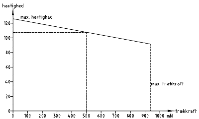
The maximum pulling force (max. trækkraft) is drawn into the load diagrams.
2.2 An example
In the example load diagram below is only shown the part that lies inside the normal working range of the locomotive.
3. When a train is pulled by two locomotives
3.1 Two similar locomotives
When two exactly similar locomotives is pulling a train you would imagine that the load is shared equally between the two so that each locomotive pull one half of the total train. If you consider the load diagram above, two locomotives of this type should be able two pull a train with a pulling force of 1000 mN when running at a speed of 107 km/h.
It is easy to test if this is correct by dividing the train in two halves and let each locomotive pull its half with a small distance between the two train halves.
Often you may observe that the two train halves are running at speeds that are a little different. This may be because the weight and rolling resistance of the two train halves are not exactly equal. It is best to use the same type of stock on both train halves, but there may be a difference anyway. The difference may be because the two locomotives are not exactly the same, this is often the case with mass-produced model locomotives.
You could swap stock between the train halves until the two train halves are running with exactly the same speed. When you couple the two train halves together the locomotives will still pull their half of the total train. Mostly it does not matter if both locomotives are placed in front or one is placed halfway down the train, only when trains are very long as seen in the USA and curves curves are tight this will matter.
3.2 Two different locomotives
When using two different locomotives you may try the same approach. It is, however, possible to see how the locomotives will behave by drawing their load lines into the same load diagram.
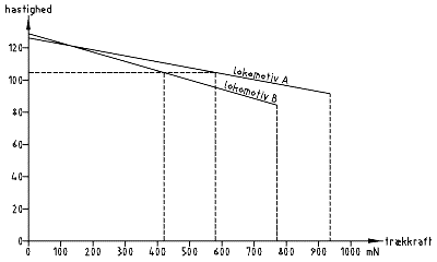
In the load diagram above locomotive A is the same as in section 2.2 while locomotive B is a little smaller than locomotive A and runs a little faster at low pulling force. Both locomotives must run at the same speed when pulling a train together so you must find the speed in the load diagram where the total pulling force of the two locomotives is 1000 mN as train from the earlier example is used. You can see that one of the locomotives is pulling more than the other.
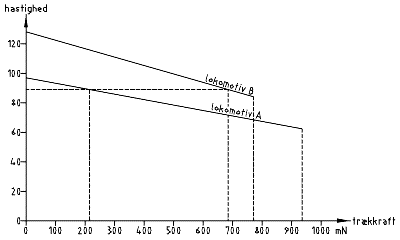
Two locomotives may, however, be too different to be able to pull a train together; below is shown another example where locomotive B is much faster that locomotive A.
4. Locomotive control
In the previous is assumed that the locomotives are supplied with a constant voltage e. g. 12 V DC.
4.1 Analogue control
When using a DC or an AC power supply you should use a voltage-stabilized supply so that the supply voltage only decreases little when current increases. The voltage drop through rails and wires cannot be avoided, however, so in practical terms the voltage at the locomotive will always decrease with increased load.
This changes nothing at the principles outlined above in that two locomotives pulling a train will reach a new working point at a little lower speed and with a little different distribution of the pulling forces. The same will happen as voltage is controlled in order to control the speed.
4.2 Digital control
With digital control the settings of the mobile decoder is adapted to the running characteristics of the locomotive at hand. If you want to run more locomotives together controlled from the same digital controller you should make an effort to match the speed settings for the locomotives that is to run together.
Newer mobile decoders is provided with load control (back EMF). This function increases the supply voltage for the motor a little when the motor current increases and hence it puts the natural load behavior of the DC motor more or less out of play. If you use load control decoders you should be particularly careful to match the running characteristics of the locomotives to each other.